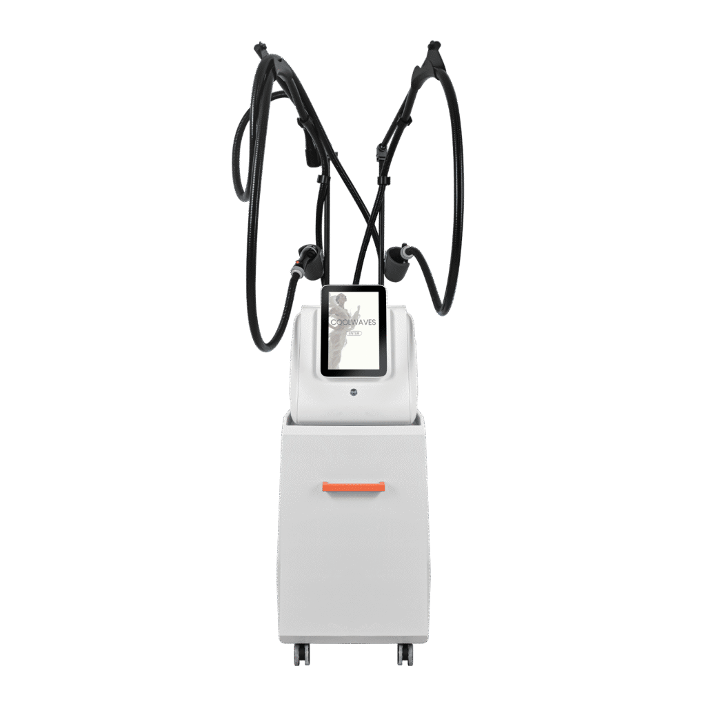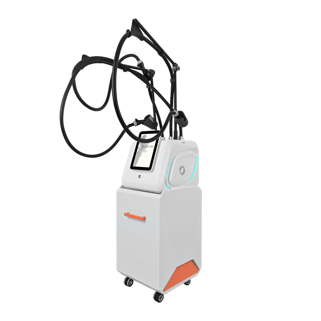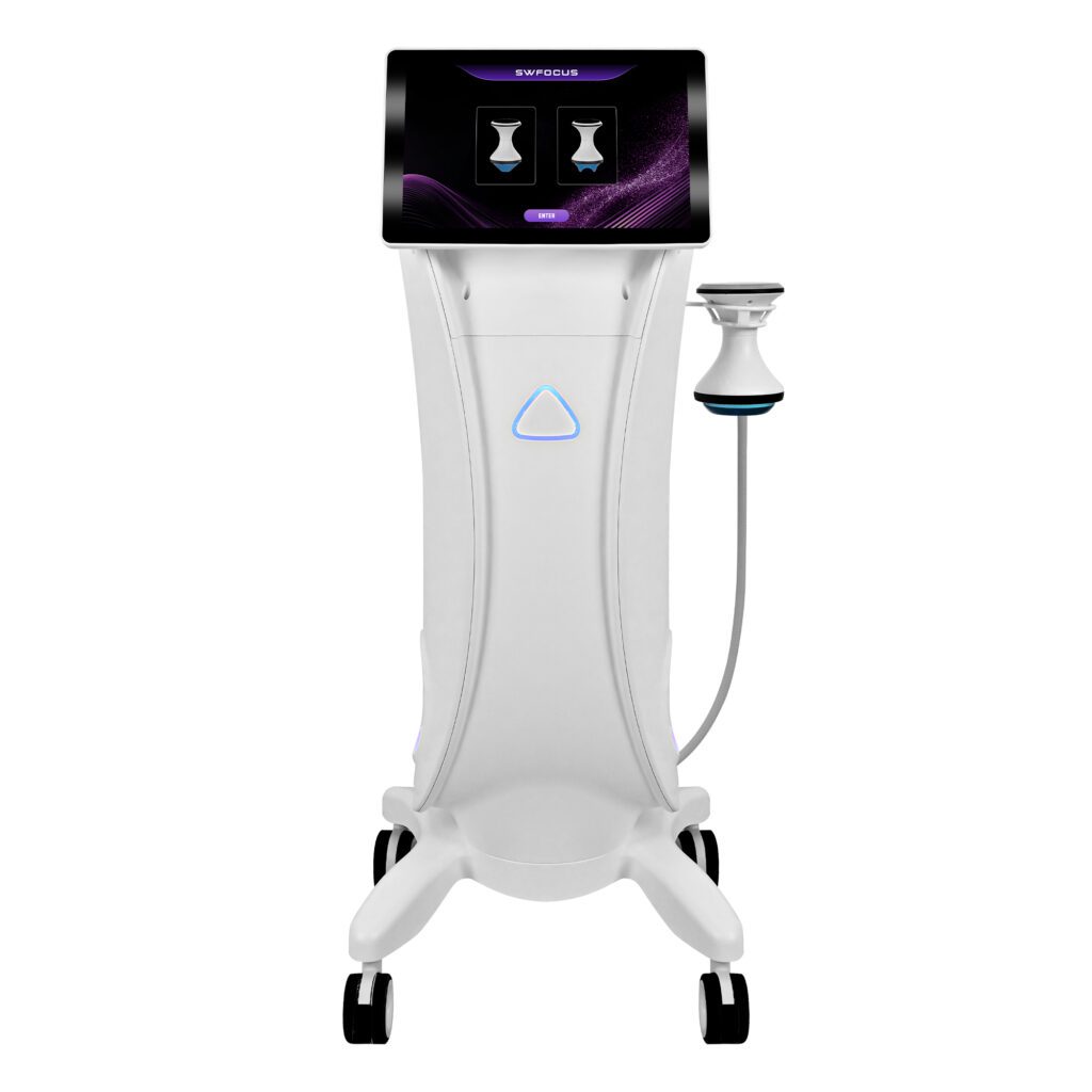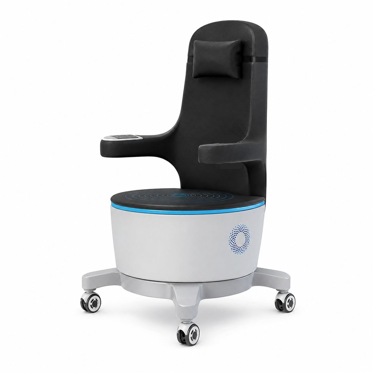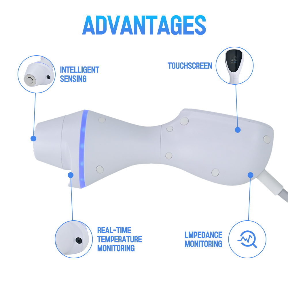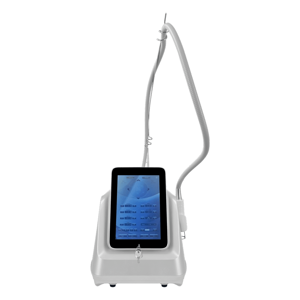

A modular beauty device can support several handles, applicators, accessories, or product variants from one technical foundation. Done well, the architecture reduces repeated engineering, creates clearer upgrade paths, and allows factories to reuse boards, displays, software services, cooling elements, housings, test fixtures, and service knowledge. Done poorly, it creates consoles with connectors that appear universal while power, parameters, software, cooling, and treatment workflows remain incompatible.
The architecture must therefore define more than a common plug. It needs stable module boundaries, explicit interface contracts, capacity budgets, item recognition, software allocation, configuration rules, verification evidence, and change governance. It should also state which elements must remain product-specific.
This guide explains how factories can structure a beauty device around a shared core and controlled modules, with particular attention to modular handles and shared components. SHEFMON products are used as public category examples; the proposed architectures are engineering frameworks rather than descriptions of confidential SHEFMON designs.
Executive Summary
A practical modular beauty device architecture should:
- Begin with product requirements, not a connector. The factory must know which users, workflows, technologies, and future configurations the architecture should support.
- Separate the stable core from variable modules. Power, control, display, software services, cooling, fluid systems, handpieces, housings, and accessories need explicit ownership and reuse boundaries.
- Define every interface as a contract. Mechanical, electrical, communication, thermal, vacuum, fluid, optical, RF, ultrasound, and user interfaces require limits and verification.
- Budget shared resources. Power, heat rejection, processor capacity, communication bandwidth, fluid flow, vacuum, space, weight, and production-test time should cover approved combinations.
- Make compatibility explicit. Physical fit cannot substitute for a controlled matrix linking console hardware, software, handle revision, parameters, consumables, and market configuration.
- Use recognition and software allocation carefully. The console should enable only the modes and boundaries approved for the connected module.
- Design against incorrect combinations. Keying, identification, software checks, configuration rules, and production controls should prevent unsupported mixing.
- Verify modules, interfaces, and complete products separately. Reusable evidence can reduce work, but every released combination still needs product-level integration and workflow evidence.
- Prepare manufacturing and service for modularity. BOMs, order codes, assembly instructions, fixtures, diagnostics, spares, and installed-base records must identify the final configuration.
- Govern the shared core as a long-term asset. One common-component change can affect several current products, future models, service inventories, and devices already installed.
The aim is controlled flexibility: a platform that accepts approved modules without turning every possible combination into an implied product.
1. What Is Modular Beauty Device Product Architecture?
Product architecture defines how a device is divided into functional and physical building blocks, how those blocks interact, and which combinations become released products.
A modular architecture may include:
- shared chassis or enclosure family;
- power and control core;
- display and user-interface layer;
- common software services;
- cooling, vacuum, pressure, or fluid infrastructure;
- technology-specific functional modules;
- modular handles or applicators;
- tips, cartridges, accessories, and consumables;
- standard production and diagnostic interfaces; and
- model-specific labels, packages, documentation, and workflows.
The modules are valuable only when their boundaries are controlled. Reusing a part informally is component copying, not modular architecture.
2. Modular Product Architecture Is Different from Portfolio Strategy
Portfolio strategy decides which products and buyer roles the company should offer. Product architecture decides how the technical system will implement those products.
Portfolio questions include:
- Which categories and buyer segments matter?
- Which models should be entry, core, premium, compact, or specialized?
- Which investments belong on the roadmap?
Architecture questions include:
- Which functions belong in the shared core?
- Which module owns a requirement?
- How does a handle receive power and communicate?
- What capacity is reserved for future modules?
- How is an unsupported combination blocked?
- Which tests can be reused?
The two disciplines inform each other, but this article concentrates on the technical arrangement inside and around the product.
3. Define the Product Family before the Shared Core
The architecture team should identify credible products and configurations first. Record:
- target businesses and professional users;
- intended service categories;
- room and workflow conditions;
- expected desktop, vertical, cart, or portable formats;
- required functions and performance envelopes;
- standard and optional handles;
- consumables and replacement model;
- regional configurations;
- production-volume assumptions;
- service and upgrade expectations; and
- plausible future extensions.
A core designed around one current model may become a constraint when another product needs more power, cooling, screen space, connectors, or software complexity.
4. Divide the Architecture into Three Reuse Classes
| Reuse class | Purpose | Examples |
|---|---|---|
| Stable shared core | Provides functions intended to remain common across approved products | Control framework, power backbone, display platform, common diagnostics |
| Controlled variable module | Connects through a defined interface and changes by model or package | Handle, pump module, RF module, cooling module, language pack |
| Product-specific element | Preserves a category, buyer, performance, workflow, or market requirement | Treatment technology, unique enclosure, category-specific controls, dedicated documentation |
The factory should resist two extremes: making everything unique and forcing every function into one universal core.
5. Create a Functional Decomposition
Start with functions rather than physical parts. A beauty device may need to:
- receive and distribute power;
- control output;
- manage temperature or cooling;
- create vacuum, pressure, movement, or fluid flow;
- recognize a connected module;
- display operating states;
- accept parameters;
- monitor sensors;
- handle warnings and faults;
- store configuration data;
- support production test and service; and
- guide cleaning, replacement, and maintenance.
Allocate each function to the shared core, a variable module, the user interface, an external accessory, or the operator workflow. Missing or duplicate ownership often causes integration problems.
6. Create a Physical Decomposition
Map the functional architecture to physical assemblies such as:
- frame, housing, cart, or desktop enclosure;
- mains input and power assemblies;
- control board and communication network;
- display and physical controls;
- cooling assembly;
- vacuum, fluid, or pneumatic assembly;
- energy or motion module;
- connector panel;
- handles and applicators;
- holders, cables, tubes, bottles, trays, and accessories; and
- package and service modules.
The physical boundary should support assembly, inspection, replacement, and version identification. A functional module that is scattered across several inseparable assemblies may not provide the expected modular benefit.
7. Write an Architecture Responsibility Matrix
| Requirement area | Shared core owner | Module owner | Product owner |
|---|---|---|---|
| Power | Defines rail limits, protection, connector budget | Defines module demand and transient behavior | Approves the released combination |
| Communication | Defines protocol, addressing, timing, and diagnostics | Implements identity and messages | Defines user behavior and compatibility |
| Cooling | Defines available capacity and monitoring | Defines heat load and local transfer | Defines duty profile and environment |
| Software | Provides platform services and module framework | Supplies module logic and data | Controls modes, parameters, workflow, and release |
| Mechanical | Defines envelope, mounting, keying, and retention rules | Fits the assigned envelope | Confirms room, operator, storage, and package needs |
| Verification | Proves shared requirements | Proves module requirements | Proves the complete configured product |
Each requirement should have one accountable owner even when several teams contribute.
8. Define Interface Control Documents
An interface control document should identify both sides of a module boundary. It can include:
- module and core identifiers;
- drawing and revision;
- mechanical envelope and mounting datums;
- connector family and keying;
- pin assignments;
- power, voltage, current, signal, and grounding limits;
- communication protocol and timing;
- coolant, airflow, vacuum, pressure, or fluid connections;
- thermal load and allowable temperature;
- identification and recognition method;
- startup, shutdown, connection, and fault behavior;
- verification method; and
- ownership of later changes.
The interface record should be controlled like a design output, not kept only in an engineer’s slide deck.
9. Do Not Treat a Common Connector as Universal Compatibility
A shared connector can simplify sourcing and assembly, but it can also invite an unsupported handle to be attached. Two modules may share the same physical connector while differing in:
- power demand;
- pin assignment;
- communication protocol;
- cooling requirement;
- vacuum or fluid path;
- parameter limits;
- software generation;
- intended function;
- production test; and
- market or professional conditions.
Use mechanical keying, electrical identification, protocol validation, software permission, labels, and configuration rules appropriate to the risk. The design should reduce dependence on operator memory.
10. Establish a Power Architecture
The shared power system should define:
- input voltage and frequency scope;
- power conversion and distribution;
- normal, peak, startup, and transient budgets;
- connector and cable ratings;
- simultaneous-load rules;
- module sequencing;
- isolation, grounding, and protection as applicable;
- sensors and fault response;
- reserve capacity; and
- production measurement points.
Every approved module must declare its load profile. Adding nominal power values is insufficient when two modules start together or when cooling demand rises during extended use.
11. Establish Thermal and Cooling Architecture
Shared cooling can include fans, heat sinks, airflow paths, pumps, radiators, reservoirs, sensors, or local module cooling.
The architecture should allocate:
- steady and transient heat load;
- coolant or airflow capacity;
- pressure or flow drop;
- inlet and outlet conditions;
- temperature limits;
- warm-up and recovery;
- filter and maintenance needs;
- condensation or leakage control;
- sensor placement;
- derating, warning, and shutdown behavior; and
- capacity for permitted module combinations.
The enclosure and cable routing are part of thermal architecture because they can change airflow and heat transfer.
12. Establish Communication Architecture
A modular system may use a shared communication bus or several interfaces. Define:
- physical layer;
- addressing and discovery;
- module identity and revision;
- message structure;
- command ownership;
- update rate and latency;
- error detection;
- connection and disconnection behavior;
- unsupported-message handling;
- diagnostic data;
- bootloader or update path where applicable; and
- compatibility across generations.
The system should distinguish a missing module, an unsupported module, and a supported module reporting a fault.
13. Design Module Recognition
Recognition may use an electronic identifier, coded connector, software configuration, physical key, barcode, RFID, or another controlled method.
The system should answer:
- What module is connected?
- Which revision is it?
- Is it permitted on this core and software build?
- Which modes and parameter ranges apply?
- Does it require calibration, pairing, or lifecycle data?
- What should happen if identity cannot be read?
- Can identity data be duplicated or corrupted?
- How is recognition tested in production and service?
Identification should support the required control without creating unnecessary cost or service complexity.
14. Use a Controlled Compatibility Matrix
| Compatibility dimension | Required relationship |
|---|---|
| Core hardware | Approved board, power, cooling, connector, and sensor revisions |
| Software | Supported firmware, interface build, and configuration data |
| Module | Handle, applicator, pump, cartridge, tip, or accessory revision |
| Function | Enabled modes and prohibited combinations |
| Parameters | Units, defaults, minimums, maximums, and step sizes |
| Consumables | Approved tips, cartridges, fluids, filters, or replacement items |
| Product | Released model and package identity |
| Region | Voltage, language, labels, manuals, and market applicability |
| Service | Replacement, update, adapter, pairing, and diagnostic rules |
The matrix should feed engineering, quotations, order configuration, production, manuals, and service rather than remain a technical reference nobody else uses.
15. Allocate Capacity Budgets
| Resource | Architecture budget questions |
|---|---|
| Electrical power | What are normal, peak, transient, and reserve limits? |
| Cooling | How much heat can the system remove under the approved environment and duty profile? |
| Processing | What CPU, memory, storage, and timing margin remain? |
| Communication | How many modules, messages, addresses, and update cycles are supported? |
| Vacuum or fluid | What flow, pressure, volume, valve, and waste capacity are available? |
| Mechanical | What space, mass, center-of-gravity, cable, holder, and access limits apply? |
| User interface | How many modes, states, parameters, warnings, and service paths remain manageable? |
| Production and service | How much test, calibration, training, and spare-part complexity can be supported? |
Budgets should be reviewed when a new module is proposed. Spare capacity is an engineering resource, not an automatic invitation to add functions.
16. Define Module Slots and Extension Points
A slot is a planned location for a class of module. It may be a physical bay, connector group, software service, mounting pattern, or fluid port.
For every extension point, define:
- intended module family;
- interface version;
- capacity allocation;
- permitted combinations;
- unused-state protection;
- identification method;
- test access;
- enclosure and storage impact;
- future revision rules; and
- conditions that require a new platform generation.
Unused ports should not expose ambiguous functions or create maintenance paths for modules the product does not support.
17. Separate Platform Services from Product Workflow
Shared software services may include:
- startup and hardware discovery;
- user and permission management;
- language and units;
- logging and diagnostics;
- communication drivers;
- alarm framework;
- software update;
- production test mode; and
- common navigation patterns.
Product-specific software should define the actual service modes, approved handles, parameters, treatment-state logic, warnings, cleaning, and operator workflow. Reusing a common framework should not expose irrelevant screens or parameters.
18. Design a Module Descriptor
A module descriptor can provide controlled data such as:
- module type;
- part number and revision;
- serial or lot identity where appropriate;
- supported interface version;
- required core capability;
- permitted modes;
- parameter boundaries;
- calibration or pairing information;
- maintenance or lifecycle status;
- diagnostic data; and
- production-test result.
The architecture should decide which data lives in the module, the console, the product configuration, or the service database. Duplicate sources need an authority rule.
19. Control Parameter Ownership
Parameters may be stored in software, a module, a product configuration file, or several places. The architecture should state:
- authoritative source;
- permitted ranges;
- default and preset ownership;
- unit conversion;
- hardware enforcement;
- user permissions;
- update process;
- behavior after module replacement;
- backward compatibility; and
- production confirmation.
A new handle should not become active with generic limits merely because the interface recognizes its identity.
20. Design Safe Mode Transitions
Multifunction platforms should define how the system moves between modules and operating states.
Review:
- module connection before and after startup;
- switching from one handle to another;
- power and cooling state during transition;
- clearing or retaining parameters;
- stopping active functions;
- shared pump, vacuum, fluid, or motor state;
- incompatible simultaneous operation;
- fault recovery;
- cleaning or consumable-change prompts; and
- return to a neutral ready state.
State logic belongs in the architecture because it crosses module and product boundaries.
21. Design the Mechanical Module Boundary
Mechanical modularity requires more than matching screw holes. Define:
- mounting datums and tolerance stack;
- insertion and removal path;
- fasteners and tool access;
- alignment and retention;
- vibration and load transfer;
- sealing and contamination boundaries;
- connector engagement;
- cable, hose, and tube bend radius;
- service access;
- holder and storage geometry; and
- protection during shipment.
A module that can be installed only by dismantling unrelated systems may be replaceable but not operationally modular.
22. Design Shared Housings Carefully
A common housing can reduce tooling and visual fragmentation, but one enclosure may not suit every module combination.
Check:
- internal volume;
- airflow and thermal path;
- screen and control position;
- number and location of connectors;
- handle and accessory storage;
- bottle, waste, filter, or coolant access;
- structural load and center of gravity;
- desktop or cart stability;
- assembly and service sequence;
- unused openings; and
- package size and protection.
Blank covers and configurable panels can support variation when their identity and assembly rules remain controlled.
23. Govern Shared Boards and Electronics
A shared control board may standardize processors, power control, communications, sensors, and diagnostics. The architecture should define:
- supported product and module classes;
- fitted versus unpopulated functions;
- board revision and firmware relationship;
- electrical capacity;
- connector options;
- production programming;
- calibration and test;
- cybersecurity or data requirements where applicable;
- component lifecycle; and
- conditions requiring a new board generation.
Do not enable unsupported functions merely because the board contains the necessary connector or circuit.
24. Govern Shared Cooling and Fluid Components
Pumps, fans, radiators, valves, reservoirs, bottles, filters, tubing, seals, and sensors may be reused when their requirements remain within a proven envelope.
For each shared component, record:
- capacity range;
- compatible media or coolant;
- pressure, flow, temperature, and duty limits;
- electrical and control interface;
- material and seal relationships;
- noise and vibration;
- maintenance and replacement;
- production inspection;
- supplier and revision; and
- products and modules covered by evidence.
Sharing a pump does not mean that the complete fluid circuit is automatically shared.
25. Govern Modular Handles and Applicators
For each handle family, define:
- functional role;
- module and revision identity;
- core hardware and software compatibility;
- mechanical and electrical connector;
- communication protocol;
- cooling, vacuum, fluid, or energy interface;
- parameter boundaries;
- recognition and fault behavior;
- cable or hose requirements;
- holder and packaging;
- production and service test; and
- compatible tips, cartridges, accessories, or consumables.
The architecture should also state whether a handle is shared across models, limited to one category, or merely uses a common physical format.
26. Prevent Unsupported Module Combinations
Use layered controls where appropriate:
- distinct part and order numbers;
- mechanical keying;
- connector coding;
- electronic identity;
- software compatibility checks;
- configuration database;
- parameter restrictions;
- assembly instructions;
- production scans or confirmations;
- final functional test;
- labels and manuals; and
- service compatibility tools.
One control may fail or be bypassed. Several consistent controls make incorrect assembly, sale, or service less likely.
27. Design Configuration Rules
A released product configuration should state:
- shared-core revision;
- category or technology module;
- enclosure and mechanical package;
- software and parameter data;
- handle and applicator set;
- optional modules;
- consumable starter pack;
- voltage, plug, language, and region;
- labels, manuals, and packaging; and
- verification status.
Rules should include required, optional, mutually exclusive, and dependent selections. A modular platform still needs a finite list of buildable products.
28. Use a Platform-Aware BOM Structure
The bill of materials can separate:
- shared core assembly;
- common electronics;
- shared software reference;
- category module;
- configuration-specific enclosure parts;
- standard and optional handles;
- regional electrical and language kit;
- consumables and accessories;
- buyer-specific OEM/ODM content; and
- service-only components.
This structure helps identify which products are affected by a shared-component change while preserving the exact content of each finished unit.
29. Verify at Four Architecture Levels
| Verification level | Main question | Example evidence |
|---|---|---|
| Component | Does the shared part meet its defined requirements? | Board, pump, screen, connector, cable, or fan tests |
| Module | Does the functional block operate within its own envelope? | Handle, cooling assembly, fluid module, or software-service tests |
| Interface | Do connected blocks exchange power, data, heat, fluid, force, and state correctly? | Boundary and fault tests |
| Product configuration | Does the selected combination meet the released product and workflow requirements? | Integrated function, usability, production, and configuration evidence |
Evidence can be reused only when the item, revision, conditions, and requirements remain applicable.
30. Test Resource Contention
Modular systems may pass one-module tests and fail when resources are shared. Evaluate:
- peak power overlap;
- processor and communication load;
- cooling recovery between modes;
- pump, vacuum, pressure, or fluid competition;
- sensor address or data conflict;
- memory or storage limits;
- user-interface state conflicts;
- connector and holder availability;
- production-test sequencing; and
- maintenance burden.
The architecture should define permitted simultaneous operation and required transitions rather than leave them to software improvisation.
31. Build Production Tests around the Architecture
Production should be able to test shared and unique elements efficiently.
Possible layers include:
- incoming shared-component inspection;
- core assembly power and communication test;
- module-level functional test;
- software loading and configuration confirmation;
- handle recognition and output test;
- cooling, vacuum, fluid, or motion test as applicable;
- product-level integration test;
- regional label and language check; and
- package completeness.
Fixtures and results should identify platform, module, and product revisions.
32. Design for Service and Module Replacement
Modularity can simplify service when the architecture provides:
- clear module identity;
- accessible replacement boundaries;
- keyed connectors;
- common diagnostic services;
- fault isolation;
- replacement instructions;
- post-repair test;
- calibration or pairing where needed;
- compatible spare-part mapping; and
- installed-base configuration records.
Replacing a module should not silently change the product configuration or introduce unsupported software.
33. Manage Shared-Component Changes
A change to a shared board, power supply, pump, connector, protocol, software service, or housing can affect several products.
The engineering change review should identify:
- all products and configurations using the item;
- current production and future development;
- interface and capacity changes;
- verification and regression scope;
- supplier and inventory impact;
- software and tool compatibility;
- service parts and installed units;
- documentation and training; and
- effectivity by platform and product.
The first product requesting the change should not define the decision for every dependent model alone.
34. Version the Platform, Modules, and Products Separately
The configuration system should answer:
- Which platform revision does this device use?
- Which core and module revisions are installed?
- Which software build supports them?
- Which handles and consumables are approved?
- Which product configuration was sold?
- Which later replacements or upgrades occurred?
Separate version identities allow the factory to evolve one module without renaming every product, while still exposing compatibility boundaries.
35. Protect the Installed Base
For every serialized unit, preserve:
- product configuration;
- platform and module revisions;
- hardware and software;
- handle and accessory package;
- regional version;
- later upgrades and repairs;
- compatible consumables and spare parts; and
- applicable manuals and service instructions.
Future modules may be backward compatible, require an upgrade kit, or be limited to new cores. The architecture and commercial data should state which case applies.
36. Control OEM/ODM Use of the Architecture
The SHEFMON OEM/ODM page describes customization in exterior and mechanical design, internal layout, handpiece connections, function, interface and language, logo, packaging, manuals, and prototyping. A modular architecture can support these variations when the project stays within approved extension points.
Define:
- standard shared core;
- customer-specific modules or cosmetics;
- interface version;
- configuration code;
- buyer-supplied materials and approvals;
- verification affected by customization;
- production and order identity;
- software branch or theme ownership;
- service and spare-part relationship; and
- rules for future changes.
Customization outside the architecture should become a separate engineering decision rather than a hidden exception.
37. A0648 Example: Facial Fluid and Handle Architecture
The official SHEFMON A0648 hydro microdermabrasion system page describes a nine-function facial device associated with hydro dermabrasion, vacuum, cleansing, extraction, and hydration roles.
For a new facial platform, architects could separate:
- shared display, power, control, and diagnostics;
- vacuum and fluid infrastructure;
- bottle, valve, tubing, filter, and waste modules;
- function-specific handles and tips;
- common connector and recognition rules;
- product-specific mode and parameter mapping;
- holder and accessory panels; and
- compact versus professional enclosure packages.
The architecture must define which handles share vacuum or fluid resources and how cleaning, leakage control, and production testing change by configuration. This is an illustrative architecture, not a disclosure of A0648 construction.
38. A0426 Example: Hair-Removal Handle and Cooling Architecture
The SHEFMON A0426 diode laser hair-removal system page publishes wavelength and spot-size choices alongside cooling, touchscreen, and language information.
For a new product family in this category, the architecture could distinguish:
- shared control, display, language, and diagnostic services;
- power and cooling tiers;
- wavelength and handpiece modules;
- spot-size identity;
- connector, hose, and holder interfaces;
- recognition and parameter data;
- product-specific duty and performance envelope; and
- regional and service configurations.
A handle should be approved only on the cores whose power, cooling, software, and production tests support it.
39. B0155 Example: Multifunction Body-Device Modules
SHEFMON’s official B0155 Desktop Endos Velapro information lists a desktop multifunction system with vacuum roller, RF, rotating massage, and 80K cavitation elements.
For a new body-care architecture, potential modules could include:
- shared screen, control, user management, and diagnostics;
- power and RF infrastructure;
- vacuum and roller module;
- rotating massage module;
- cavitation module;
- handle-recognition framework;
- desktop or cart enclosure variants;
- cable and holder panels; and
- configuration-specific workflows and tests.
The architecture must define resource conflicts and permissible combinations instead of assuming every function can operate together.
40. A0152 and A0204 Example: Keep Advanced Categories Bounded
The SHEFMON A0152 RF microneedling system and A0204 9D/7D focused HIFU system illustrate categories where handles, needle tips, treatment cartridges, parameters, recognition, consumables, and professional workflows can strongly shape the product.
These systems might share selected displays, software services, housings, manufacturing resources, or diagnostic patterns. Their technology-specific modules, parameters, consumables, validation, documentation, and intended workflows may still require firm separation.
Modular architecture should preserve meaningful technical boundaries rather than create a superficial universal console.
41. Common Modular-Architecture Failures
Avoid:
- designing a connector before defining product requirements;
- calling visually similar parts shared without common specifications;
- assuming physical fit proves compatibility;
- allocating no reserve capacity;
- exposing unused connectors or software modes;
- storing parameter limits in several uncontrolled places;
- reusing a screen without reviewing product workflow;
- approving modules individually without integration testing;
- allowing OEM customization to bypass interface rules;
- using a shared part number for incompatible revisions;
- changing a core component for one product without portfolio impact review;
- releasing unlimited theoretical combinations; and
- losing platform and module identity in service records.
These failures turn modularity into hidden variation rather than controlled reuse.
42. Modular Beauty Device Architecture Checklist
- Target products, users, workflows, environments, and future extensions are defined.
- Stable core, variable modules, and product-specific elements are separated.
- Functional and physical decompositions are complete.
- Every requirement and interface has an accountable owner.
- Mechanical, electrical, communication, thermal, cooling, vacuum, fluid, energy, software, and user boundaries are defined as applicable.
- Power, cooling, processing, communication, space, weight, fluid, interface, and test capacity budgets are controlled.
- Module slots and extension points have versioned rules.
- Recognition identifies approved module and revision states.
- Compatibility links core, software, module, function, parameters, consumables, product, region, and service.
- Unsupported combinations are blocked through layered controls.
- Shared software services remain separate from product-specific workflow and parameter logic.
- Mechanical design supports assembly, test, replacement, storage, and shipping.
- Configuration rules define required, optional, dependent, and mutually exclusive selections.
- BOMs separate shared core, product module, handles, regional kit, and customer-specific content.
- Component, module, interface, and product-level verification are planned.
- Production fixtures and records identify platform, module, software, and product revisions.
- Service replacement preserves configuration and compatibility.
- Shared-component changes review every dependent product and installed unit.
- OEM/ODM variants use approved extension points or enter separate engineering control.
FAQ
1. What makes a beauty device handle truly modular?
A modular handle has defined mechanical, electrical, communication, cooling or fluid, software, parameter, recognition, production-test, and service interfaces. It is approved for named console and software configurations rather than merely sharing a connector.
2. Should every beauty device use a universal handle connector?
No. A common connector can reduce part variety, but it can also enable incorrect combinations. The choice should follow product requirements, interface limits, keying, recognition, risk, service, and future platform needs.
3. What belongs in the shared core?
Functions with stable requirements across several credible products may belong in the core, such as selected power, control, display, communication, diagnostics, or manufacturing resources. Category-specific technology and workflow should remain modular or product-specific.
4. How much reserve capacity should a platform include?
The amount depends on the approved roadmap, uncertainty, cost, size, heat, and expected modules. Record explicit power, cooling, processing, communication, mechanical, and service budgets rather than adding unspecified extra capacity.
5. Can one software build support several beauty device models?
It can when the architecture controls hardware detection, product configuration, modes, parameters, permissions, languages, diagnostics, and regression testing. A shared codebase still needs identifiable builds and product-specific release evidence.
6. How should factories prevent the wrong handle from operating?
Use an appropriate combination of part identity, mechanical keying, connector coding, electronic recognition, software compatibility checks, parameter restrictions, assembly controls, final testing, labels, and service tools.
7. Can validation evidence be reused for a shared module?
Yes, when the module revision, interface, conditions, requirements, and operating envelope remain applicable. The factory should document why the evidence covers the new product and still test complete product integration.
8. How are modular products represented in the BOM?
Use separate structures for the shared core, category module, product enclosure, software reference, standard and optional handles, regional kit, consumables, accessories, and customer-specific content.
9. How does modular architecture affect service?
It can simplify diagnostics and module replacement, but technicians still need installed configuration, compatible software, replacement rules, calibration or pairing, post-repair tests, and controlled spare-part mappings.
10. How can an OEM/ODM buyer discuss a modular product with SHEFMON?
Prepare the target product role, required functions, preferred handles, expected variants, destination markets, interface needs, branding, software, packaging, service expectations, and future expansion ideas. Then contact SHEFMON to discuss a standard configuration or controlled development project.
Conclusion
Modular beauty device architecture creates value when it converts reuse into explicit engineering rules. The stable core, variable modules, and product-specific elements need clear responsibilities. Their interfaces need measurable limits, and every released combination needs a defined configuration and appropriate evidence.
The strongest architecture also plans for production, service, and evolution. Shared components should reduce repeated work without hiding product differences. Modular handles should expand approved capability without exposing unsupported modes. Platform changes should remain traceable across current models and installed units.
Explore the SHEFMON beauty device portfolio, review its OEM/ODM capabilities, or contact SHEFMON to discuss a standard device configuration, modular handle package, or product-development requirement.